Deployable Rover
Click to jump to details ↓
 2018
2018
Zenith - 2018 Rocketry Project
Designed and manufactured over the course of the 2017-2018 NASA Student Launch season, "Zenith" measures up to be the 2nd tallest vehicle built by River City Rocketry. The rocket, coming in at 11' 7" and 50 lbs, and uses an Aerotech L2200 with a vivid Mojave green flame. The airframe of the vehicle was made in house by team members. The rocket carries the team designed VDS, an autonomous deployable Rover, and custom parachutes cut and sewn by the team.
Flight History:
The vehicle's nosecone consists of a customized parabolic geometry, optimized for the vehicle's 0.7 Mach ascent. The nose cone was 3D printed out of Nylon 12 at University of Louisville's Rapid Prototyping Center.
The Rover payload payload mounts on a custom designed and manufactured Rover Bearing System (RBS) that allows the entire Rover to rotate inside the mainframe upon landing. This ensures that the Rover will deploy without orientation restrictions. Upon exiting the air frame, the Rover uses a Lidar sensor to map and navigate through any debris on the field. After driving 5 feet, the Rover stops and actuates its solar array tower, allowing 4 solar panels to rotate from their stowed configuration. In the spirit of the rover challenge, an HD camera takes a picture of the Rover in its surroundings for later review.
Zenith features two custom built high drag, low volume toroidal main parachutes and two cruciform drogues. The panels are laser cut with precision and sewn together in house. The custom deployment bags feature rip-stop nylon lining and shroud line stow loops to ensure orderly and reliable deployment of the main parachutes.
The Variable Drag System (VDS) is housed in the booster section of the rocket. Here, its two parts, the avionics and the drag blades, are connected through a bulk plate and stowed together in their own coupler. The avionics take live data throughout the flight to autonomously control the drag blades, which deploy through the slots after burnout, and retract back into the rocket upon apogee for a safe recovery. The avionics also send this live data to a ground station, where the status of the VDS can be monitored telemetrically.
Mission Context (2017-2018 NASA Student Launch Handbook 4.5.1 - 4.5.4): Teams will design a custom rover that will deploy from the internal structure of the launch vehicle. At landing, the team will remotely activate a trigger to deploy the rover from the rocket. After deployment, the rover will autonomously move at least 5 ft. from the launch vehicle. Once the rover has reached its final destination, it will deploy a set of foldable solar cell panels.
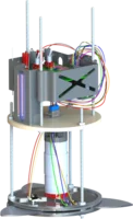
The ROCS is a unique bearing system designed to support the rover payload throughout the flight of the launch vehicle and ensure upright orientation of the rover after landing regardless of the orientation of the payload bay. The bearing rings have been custom designed and machined by the team out of tool steel. The bridging sled connecting the two rings has been precisely cut using a CNC water jet.
The RLM is a device that retains the rover payload in the airframe of the launch vehicle throughout the flight. A loading arm matches with a bracket on the rear of the rover to lock the rover along the central axis of the launch vehicle. This in conjunction with a female T-slot mounted on the ROCS bridging sled and accompanying male T-nut on the bottom of the rover fixes the rover along all axis. After receiving the deployment signal, the rover unlocks the loading arm and drives forward off the T-slot.
The DTS allows the team to deploy the rover from a linear distance of over 1 mile away. A receiver module has been secured inside the airframe. To mitigate the issue of signal loss through the carbon fiber airframe and ensure signal reception in all directions, a flexible antenna has been wrapped around the exterior of the airframe. A Yagi antenna is being used to directionalize and increase the range of the transmitter signal.
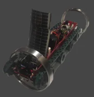
The RBS acts as the main support for all on-board rover subsystems and electronics. The body has been water jet out of aluminum, bent using a manual finger break, and welded along the corners. The body has gone through an anodizing process carried out by the team to dye the aluminum Red Bordeaux.
The RDS consists of two main drive motors that transfer power to the main drive axles through a set of 90° bevel gears. A set of pulleys and passive wheels guide a custom designed tread as it drives the rover forward. The split saw-tooth, polyurethane tread with a high friction coating has been designed to maximize the climbing ability and traction of the rover on all terrains, both wet and dry.
The OAS is a lidar sensor mounted to the front of the rover for the purpose of detecting insurmountable objects in the path of the rover and determining a path to avoid the obstacle. Custom designed 3D printed mounts allow the sensor to be attached to a micro servo motor that increases the field of view of the sensor to 180°. An algorithm has been written to determine the path of least obstruction for the rover to turn to in the event that an object is detected.
The SAS is a deployable solar array consisting of 4 thin film, flexible solar panels. The system actuates a tower assembly by releasing a spring hinge giving vertical clearance for the panels to unfold properly and without damage. The system also utilizes a unique rotational deployment method to unfold the array in a cascading manner. After the rover has reached its final position at least 5 feet away from the launch vehicle, the array will be deployed and begin harvesting solar energy that will be used to trigger the Surface Imaging System.
The SIS has been added as a secondary mission of the payload to embrace the mindset of the rover challenge of deploying an autonomous rover vehicle on a foreign planet to collect scientific data. The system consists of a high-resolution camera module mounted to the same servo motor used by the Obstacle Avoidance System to increase the field of view of the camera and thus, the scientific data collected. The system is triggered to begin sweeping the camera and taking images based on the amount of energy collected by the Solar Array System.
The CES handles all autonomous controls and sensor data for the payload. The system consists of a control stack of 3 boards (a micro-controller, data logging board, and motor driver) along with a set of two high precision inertial measurement units mounted on a custom designed printed circuit board. The system recognizes a unique deployment signal from the DTS, performs a orientation safety check, unlocks the RLM, and commands the rover through its primary and secondary missions. The data logging board records all sensory data, images, and commands during key phases of the mission on a microSD card for analysis after retrieval of the rover.
The VDS is an air-braking system designed to deliver a high-powered rocket to precisely one mile AGL. The VDS does this by actuating three aluminum drag blades into the airstream surrounding the rocket, actively changing the vehicle's drag profile on ascent. The system responds to sensor data taken in real-time and ensures that the vehicle has the correct balance of kinetic and gravitational potential energy at all points in the flight to reach one mile AGL exactly. In the NASA Student Launch competition flight, the VDS successfully delivered the launch vehicle to 5,303 ft.: only 23 ft. from its target. The VDS also contributed to the team's Vehicle Design Award.
To predict the performance of the VDS and the launch vehicle, the team developed a simulation in Mathworks' Simulink shown to the right. This simulation allows the team to predict mission performance for each launch with unique and customizable weather scenarios, 6DOF equations of motion, and a launch animation. Future improvements include a better aerodynamic model and hardware in the loop capabilities.
To ensure the VDS would be able to withstand the predicted flight loads, FEA simulations were performed. An FEA simulation for a single drag blade as well as the entire VDS assembly was performed. The FEA simulations were used to justify material selection and determine the critical dimensions of key components.
The embedded software for the VDS is written in a combination of C and C++, it is organized over five classes, and can currently operate at a speed of 90 Hz. This code is responsible for communicating with multiple sensors to determine the state of the vehicle, processing that data, and actuating the drag blades. The code does all of these things by integrating pressure, accelerometer, gyroscope, and magnetometer readings together with a Kalman filter.
The VDS has been demonstrated to successfully deliver the launch vehicle to one mile AGL +/- 23 ft. The thorough documentation of this system, the attention to detail in simulation, and its successful performance were all cited as contributing factors to the team receiving the Vehicle Design Award at the end of the 2016-2017 season.